

The demonstration scenario, illustrated in Figure 1, is composed of a Primary User (PU) transmitting to a Primary Base Station (BS) and two Secondary Users (SU1 and SU2) transmitting to a Secondary Base Station. Since all users will utilize the same frequency and be transmitted at the same time, the two Secondary Users will be perceived as interference by the Primary BS. Therefore, a precoding algorithm is required to code all users’ data before transmission to enable the proper data decoding at the Base Station. The precoding and decoding algorithms were implemented in Xilinx System Generator in the HETCOP project.

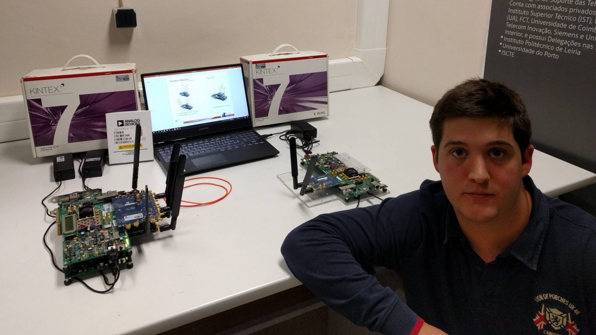
The proposed scenario has three users that need, in total, 5 transmitter (Tx) and 3 receiver (Rx) antennas. Therefore, 1 FMCOMMS5 and 1 FMCOMMS3 RF boards were required to accomplish all the RF chains required by the three users on the User Equipment side (UE).

The hardware project, responsible for configuring the RF boards, was designed from scratch with the Xilinx KC705 development kit in mind. The KC705 only has two FMC connectors, thus another FPGA was required to have the FMCOMMS3 and FMCOMMS5 RF boards. Thus, a high-speed connection between both FPGAs was required to ensure the synchronisation between all three users’ transmissions. Therefore, both boards were connected via fibre optics (SFP+) using a Aurora encoder that was integrated into the OFDM engine and MU-MIMO precoding developed in Xilinx System Generator.


The Base Station side onlyrequires one transmitter and two receiver antennas. To implement it a KC705 FPGA development kits and one FMCOMMS3 RF card was used.

